 |
| Pat LeBlanc's Lunar Module Custom Part 2 - Crew Compartment |
As with most of my projects, I began by searching the internet for information on
the real thing. There are tons of sites with diagrams and pictures but very few
with detailed dimensional data. However, I found a document titled "The Lunar
Module News Reference" (LMNR) that provided what I needed to get started (I also
borrowed my nephew's 1/48 scale LM).
Since the ascent stage is more complicated than the descent stage, I decided to
start with it. The ascent stage is divided into three parts: crew compartment,
midsection and equipment bay. Of these three, the crew compartment is the most
complex shape so I started with it With the amount of detail I was able to
gather, I decided to try to create the interior as well so that Matt could ride
inside. Borrowing an idea from the 1/48 scale LM, the crew compartment would
detach from the midsection.
According to the LMNR, the diameter of the crew compartment is 92". At 1/12
scale, that is about 7.66" (which I rounded up to 7.75"). I had some .03" thick
sheet styrene that I wanted to use for the cabin wall. It's tough enough not to
need interior supports but it's also hard to bend. I decided to use .1" thick
Plexiglas disks as bulkheads to form the Styrene into the required round shape.
I had to build a jig that would let me cut large radius disks with my band saw.
 |
Bulkhead Jig
|
I cut two 7.75" diameter Plexiglas disks and assembled them with some machine screws and nylon spacers. I then experimented with strips of construction paper to determine the length required to cover the circumference of the disks (yeah, I know pi times the diameter, but this is the real world). Next I tried forming a Styrene strip into a hoop around the disks. Once the final circumference was determined (24.375"), I layer out the cuts required to form the side of the "face" using the 1/48 scale LM as a guide. Again, first with construction paper, then with Styrene. The largest piece of Styrene I had was 17" long so I had to splice two smaller pieces together and join them with metallic duct tape. This picture shows the Styrene layer out next to the bulkhead assembly.
 |
Brow Construction
|
The most complicated shape of the crew compartment is the "brow ridge" above the windows. I decided to use balsa wood because it's easy to cut and still rigid enough to hold the Styrene in the round shape. I got a 3" x 3" x 8" block of balsa wood and cut it to the 7.75" diameter with my band saw. I put the rounded shape in place at the top of the hoop and used the edge of the Styrene as a guide to trace the required shape onto the wood. I cut the plan view then marked the front and cut where the windows would go (again using the 1/48 scale LM as a guide). Finally I trimmed the back or interior edge to minimize interference with the astronauts' heads. The brow ridge is secured to the Styrene with metallic duct tape. The strips are 2" long and .25" wide. Here's a picture of the blocks the brow ridge was cut from.
 |
Constructing the Face
|
The bottom portion of the front of the face is half of a Plexiglas disk. According to the LMNR, the forward hatch is 32" square which scales down to 2.666" (I used 2.625"). I cut an opening in the face and traced it onto another piece of Plexiglas to create a matching hatch. I covered the back of the hatch with a piece of Styrene and used tape as a hinge so that the hatch swings inward (the fact that the hatch swung in toward Buzz Aldrin was one of the reasons why Neil Armstrong was the first out onto the surface). I added a handle to "lock" the hatch in the closed position. The half disk is secured to the Styrene hoop with metallic duct tape.
 |
Facets and Duct Tape
|
The next part of the face is the slanted portion that connects the vertical half disk to the brow ridge. I used my band saw to bevel (~60 ) the edge of a piece of Plexiglas and placed the edge under the brow ridge. Again using the Styrene walls as a guide, I traced the contours onto the Plexiglas and cut it to fit in
the remaining opening. Using the 1/48 scale LM as a guide, I also cut the openings for the bottoms of the windows. The Plexiglas is secured to the Styrene and the half disk with strips of metallic duct tape.
The final part of the face is the area between the windows that houses the rendezvous radar and other instruments. The back of this area also provides a place to mount the control panels inside the crew compartment. While these pieces incorporate straight cuts, they turned out to be the most challenging
because they come in contact (at various angles) with every other piece described so far. After several attempts, I finally got an acceptable fit and secured the Plexiglas sides to the face and cabin walls with metallic duct tape. The front panel is also Plexiglas.
 |
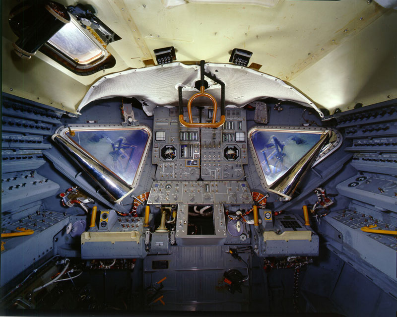
Original LM Panels
|
 |
Interior Mock-up
|
According to the LMNR, the floor of the crew compartment is 55" wide by 36" deep (I scaled it down to 4.5" by ~3"). I glued a piece of aluminum angle to the inside of the half disk to support the floor just below the hatch opening.
When I found some detailed drawings of the LM control panels, I decided I could reduce them and add some detail to the interior. I added some Plexiglas panels to mount the vertical displays and put in a shelf for the astronauts to stand in front of.
 |
Dowels as Thrusters
|
 |
| Thrusters |
Two of the RCS thruster quads are mounted on the crew compartment. I used concave portions of the balsa block that were left over from the brow ridge and trimmed them to the proper shape. To make the thruster nozzles I took pieces of 1/2" wooden dowel and used my drill press like a lathe the get the bell shape. I then covered the nozzles with 1/16" strips of metallic duct tape.
 |
Original Ascent as a Guide
|
As I mentioned above, I wanted to be able to place astronauts in the crew compartment. The manufacturer of the 1/48 scale model accomplished this by hinging the crew compartment and the midsection. I decided to install powerful magnets inside of the aft bulkhead and will put matching magnets inside the
midsection.
The real LM's were covered with various types of insulation and micrometeorite shielding. Based on available pictures, different LM's were covered in different patterns of black, gold and aluminum. I planned to use flat black paint and aluminum foil to match the pattern I found for Apollo 17's LM, Challenger. The majority of the crew compartment is black with small areas of aluminum. Therefore, it made sense to paint the exterior black and add the aluminum afterward.
 |
Applying Packing Tape
|
Before painting, I wanted to cover up the somewhat irregular surface formed by the strips of tape that hold the various pieces together. I decided to use ordinary paper covered with clear packing tape. The packing tape provides a tough, water-proof surface and the paper smooths out the ridge pattern underneath. The paper/tape is attached with Elmer's glue.
 |
Flat Black Paint
|
 |
Gold Foil Source
|
The next step was to paint the exterior flat black. Now it was time to add the aluminum. I cut pieces of aluminum foil and attached them (dull side out) to the exterior. The small amount of gold foil around the front hatch is from a Hershey "Special Dark" chocolate bar (I'm going to get really fat when it's time to cover the descent stage).
|
Checking the Scale
|
I sprayed on five coats of a matte lacquer to protect the surfaces. The front windows as well as the docking window above the Commander's station are Plexiglas. I used my drill press as a lathe again and turned the rendezvous antenna dish out of a piece of balsa wood. Here's a picture of the 1/48 scale LM next to the 1/12 crew compartment and the Major.
You can contact Pat through Facebook about his amazing custom here.
All Mattel images and captions are copyright Mattel and used without permission. All other content, including images and editorial, is Copyright © 1997-2023 John Eaton and/or contributors unless otherwise stated. If there are any comments or objections, please contact John Eaton.


No comments:
Post a Comment